3830 Trailer Outlet Wiring Diagram

Wiring Diagram For A Ford Tractor 3930 The Wiring Diagram Wiring Diagram Wiring Diagram Ford Tractor 2310 Ford Tractors Tractors Ford

Led Light Bar Relay Wire Up At Wiring Diagram For 12v Led Lights In Motorcycle Wiring Light Switch Wiring 12v Led Lights

2 Way Rocker Switch Wiring Diagram Motorcycle Wiring Light Switch Wiring 12v Led Lights

Wiring Diagram For House Light Bookingritzcarlton Info Home Electrical Wiring Electrical Wiring Light Switch Wiring

New Wiring Diagram For Multiple Lights On A Three Way Switch Diagrams Digramssample Diagramimages C Three Way Switch Light Switch Wiring Ceiling Rose Wiring

Boat Stereo Wiring Diagram Pioneer Car Stereo Sony Car Stereo Pioneer Radio
We re happy to help guide our customers to the right trailer or snow plow for them.
3830 trailer outlet wiring diagram. And we offer so much more than that. Variety of 7 pin round trailer wiring diagram. Use the rv electrical diagram we made below to get an understanding of what powers what and to learn how an rv electrical system works. As the name implies they use four wires to carry out the vital lighting functions.
For wiring in series the terminal screws are the means for passing voltage from one receptacle to another. Typical trailer wiring diagram and schematic. Use only the needed wires and ignore the others. To connect the electric system of your trailer to the vehicle you will be using special connector.
Expand the same for additional axles. Rv electrical diagram wiring schematic understanding you campers electrical wiring can be very confusing. Multiple outlet in serie wiring diagram. Only the blue brake and white ground wires are different.
The image above shows a single axle trailer and the next image shows wiring for tandem axles. 4 way trailer connectors are. They also provide a wire for a ground connection. To wire multiple outlets follow the circuit diagrams posted in this article.
4 way trailer connectors are typically used on small trailers such as boat snowmobile utility and other trailers that that do not use brakes. Stop into our harrisburg pa dealership today or call to learn more. It reveals the parts of the circuit as simplified forms as well as the power and also signal links between the tools. Above we have describes the main types of trailer wiring diagrams.
7 way trailer plug wiring diagram ford a newbie s overview of circuit diagrams. Complete with a color coded trailer wiring diagram for each plug type this guide walks through various trailer wiring installation solution including custom wiring splice in wiring and replacement wiring. If your vehicle is not equipped with a working trailer wiring harness there are a number of different solutions to provide the perfect fit for your specific vehicle. A wiring diagram is a simplified standard pictorial depiction of an electric circuit.
A very first look at a circuit layout could be complicated yet if you can check out a subway map you could check out schematics. These 2 wire diagrams fit the needs of most trailers. The four wires control the turn signals brake lights and taillights or running lights. Any break or malfunction in one outlet will cause all the other outlets to fail.
Below is the generic schematic of how the wiring goes.
Diagram Simple Computer Wiring Diagrams Full Version Hd Quality Wiring Diagrams Firststepdfw Jepix Fr

Electric Fans With Relay Wiring Electricity Automotive Mechanic Electric Fan

Wiring Diagram Of Motorcycle Honda Xrm 110 Http Bookingritzcarlton Info Wiring Diagram Of Motorcycle Honda Xrm 110 Honda Motorcycles Honda Motorcycle

How To Properly Vent Your Pipes Plumbing Vent Diagram Plumbing Vent Airstream Rv Water

H4 Led Wiring Diagram Land Rover Defender Headlight Wiring Upgrade S Musings In Diagram Headlights H4 Led Land Rover Defender Fuse Box Jeep Cherokee Headlights

2 Way Switch With Power Feed Via The Light Switch How To Wire A Light Switch Home Electrical Wiring Electrical Wiring Electrical Projects

Diagram Home Fax Wiring Diagrams Full Version Hd Quality Wiring Diagrams Refrigerationdiagrams Lineakebap It

12 Electric Hoist Wiring Diagram Wiring Diagram Wiringg Net In 2020 Electric Winch Winch Diagram

50 Free Harley Davidson Wiring Diagrams Ma4g I 2020 Kopplingsschema

Diagram In Pictures Database 6 Connector Wiring Diagram Just Download Or Read Wiring Diagram Diagram Under Tongue Onyxum Com
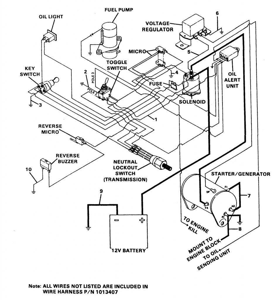
Diagram Club Car Gas Wiring Diagram Full Version Hd Quality Wiring Diagram Luta Livre Hannover Organigenialiband It

Suzuki Ts125 Wiring Diagram Suzuki Ts125 Motorcycle Wiring Motorcycle Design

Diagram Tail Light Wiring Diagram Ford 550 Full Version Hd Quality Ford 550 Educationview Seth Survivalisme Fr

