7 Pin Trailer Wiring Diagram With Brakes Disconnect
Wiring Trailer Lights With A 7 Way Plug It S Easier Than You Think Etrailer Com
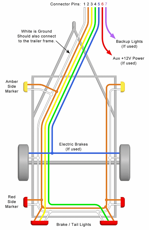
Trailer Wiring Diagram Lights Brakes Routing Wires Connectors

7 Blade Wiring Diagram Trailer Wiring Diagram Trailer Light Wiring Flatbed Trailer
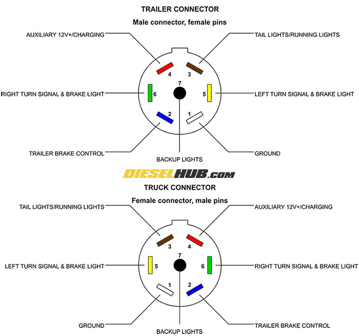
Trailer Connector Pinout Diagrams 4 6 7 Pin Connectors
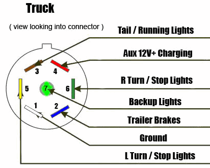
7 Way Diagram Aj S Truck Trailer Center

Wiring Diagram For Trailer Light 7 Pin Http Bookingritzcarlton Info Wiring Diagram For Trailer Light Trailer Light Wiring Trailer Wiring Diagram Car Trailer
7 pin trailer wiring diagram with brakes amazing 7 wire trailer 7 pin trailer wiring diagram with brakes.
7 pin trailer wiring diagram with brakes disconnect. This is an extension of the 7 pin flat. This is not shown in the trailer wiring diagram above. Each component ought to be set and connected with different parts in particular manner. Small 7 pin round qld identifying.
The diagram is the new zealand standard for the 7 pin flat trailer plug used on prescott trailers. Some places label the 5th pin for reverse lights. 7 pin trailer wiring diagram with brakes 7 pin flat trailer wiring diagram with brakes 7 pin rv trailer wiring diagram with brakes 7 pin trailer wiring diagram with brakes every electrical arrangement is made up of various different parts. On the tow vehicle end this should be the pin in the 5 o clock position see attached photo.
Wiring diagram comes with a number of easy to adhere to wiring diagram instructions. If not the arrangement will not function as it ought to be. Call to discuss freephone. Also some trailers with hydraulic brakes use this 5th pin to disable the brakes when the vehicle is reversing.
The diagram is the new zealand standard for the 7 pin flat trailer plug used on prescott trailers. Pins 2 and 5 are not used on our standard range of trailers. Complete with a color coded trailer wiring diagram for each plug type this guide walks through various trailer wiring installation solution including custom wiring splice in wiring and replacement wiring. This vehicle is designed not only to travel one place to another but also to take heavy loads.
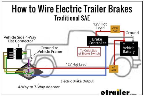
The 7 pin flat plug will fit into a 12 pin flat socket and work perfectly. If the 7 way connector on your 7 way doesn t get 12v power when the manual override is used then you will want to sever the brake controller wire that goes to the 7 way about 6 inches away from the brake controller. Various connectors are available from four to seven pins that allow for the transfer of power for the lighting as well as auxiliary functions such as an electric trailer brake controller backup lights or a 12v power supply for a winch or interior trailer lights. These directions will likely be easy to grasp and apply.
All diagrams are as viewed from the cable side see example above. Certainly that works but make sure to note it on the trailer because blue is the color for brakes. It really is supposed to assist all of the typical person in developing a correct program. This article will be discussing 7 pin semi trailer wiring diagram.
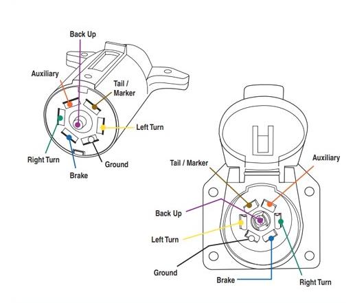
This should send 12v power to the pin on the 7 way that activates the trailer brakes. If your vehicle is not equipped with a working trailer wiring harness there are a number of different solutions to provide the perfect fit for your specific vehicle. 7 way plug wiring diagram standard wiring post purpose wire color tm park light green battery feed black rt right turn brake light brown lt left turn brake light red s trailer electric brakes blue gd ground white a accessory yellow this is the most common standard wiring scheme for rv plugs and the one used by major auto manufacturers today.

7 Pin Trailer Plug Light Wiring Diagram Color Code Trailer Wiring Diagram Trailer Light Wiring Boat Trailer Lights
How To Wire Lights On A Trailer Wiring Diagrams Instructions

Wiring Diagram For Trailer Hookup Http Bookingritzcarlton Info Wiring Diagram For Trailer Hookup Trailer Light Wiring Trailer Wiring Diagram Rv Solar Power

Wiring Diagram For Gm Trailer Plug Powerking Of 7 Pin Wiring Diagram Ford On Chevy Trailer Wiring Diagr Trailer Wiring Diagram Trailer Light Wiring Rv Trailers

Trailer End Pollak Wiring Pk12706 Trailer Wiring Diagram Trailer Light Wiring Electrical Plug Wiring

Pin By Lucas Mosley On Electric Wiring Trailer Light Wiring Utility Trailer Trailer Wiring Diagram

Wiring Diagram For Trailer Light 7 Pin Http Bookingritzcarlton Info Wiring Diagram For Trailer Light Trailer Wiring Diagram Trailer Light Wiring Electricity

Trailer Wiring And Brake Control Wiring For Towing Trailers Trailer Wiring Diagram Towing Trailer Trailer
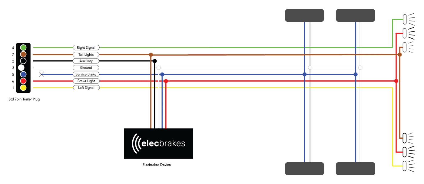
Electric Brake Controller Wiring Diagram Elecbrakes

Pin On Camper Vans

Trailer Wiring Diagrams For Single Axle Trailers And Tandem Axle Trailers Trailer Wiring Diagram Trailer Light Wiring Utility Trailer

Horse Trailer Electrical Wiring Diagrams Lookpdf Com Result Electric Trailer Brake Wiring Diagr Trailer Wiring Diagram Boat Trailer Lights Horse Trailer

How To Remove Scratches From Plastic Trailer Wiring Diagram Trailer Light Wiring 5th Wheel Trailers

