Boatmate Trailer Wiring Diagram

Oval Led Truck And Trailer Lights 6 Brake Turn Tail Lights 3 Pin Connector Flush Mount 10 Leds Truck And Trailer Tail Light Trailer

How To Rewire Your Boat Trailer Tekne Yapimi Tekne
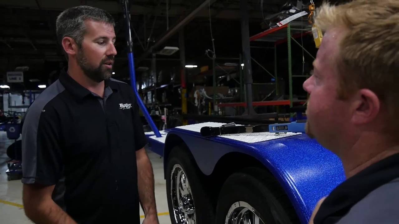
Boatmate Service Video The Answers To Many Of Your Service Questions Youtube

Boatmate Trailer Parts Boat Mate Trailer Wheel Bearings Trailers For Sale Malibu Boats Trailer

Boatmate Trailer Parts Malibu Boatmate Trailer In 2020 Malibu Boats Wheels For Sale Custom Trailers

Trailer Not Reversing Trailers Tow Rigs Themalibucrew Com
Lane street maryville tennessee 37801 phone.
Boatmate trailer wiring diagram. You would just need to match the colors of the connector to the wiring of your trailer. If not the arrangement will not function as it ought to be. The coupler assembly is known as an actuator and contains a master brake cylinder similar to that in an automobile. All of the whites would need to run to the single white wire of the 4 way but the rest of the wires would match right up.
7 pin trailer wiring diagram with brakes 7 pin flat trailer wiring diagram with brakes 7 pin rv trailer wiring diagram with brakes 7 pin trailer wiring diagram with brakes every electrical arrangement is made up of various different parts. The wires on the brakerite system wiring harness are approximately 2 metres long see page 9 to allow for flexibility when mounting the unit however extensions may be required to connect unit to the trailer s electrical wiring. This works for fresh water but for the salt use crimp connectors with heat shrink collars to connect all of the lights. When the brakes are applied in the tow vehicle the trailer surges against the tow ball forcing fluid through the trailer hydraulic system thus applying the trailer brakes.
Many trailer brands use simple pinch wire connectors to cut through the insulation to tie the positive 12 volt pigtail from the running and clearance lights into the main wires. This molded 7 way rv style trailer end connector with a 22 long cable lets you replace a damaged wiring harness on your trailer. When making connections to the trailer s wiring harness the desired termination is a solder joint. The white is ground.
Your browser does not support html5 video. The coupler assembly is known as an actuator and contains a master brake cylinder similar to that in an automobile. When the brakes are applied in the tow vehicle the trailer surges against the tow ball forcing fluid through the trailer hydraulic system thus applying the trailer brakes. Similar expert q a pages.
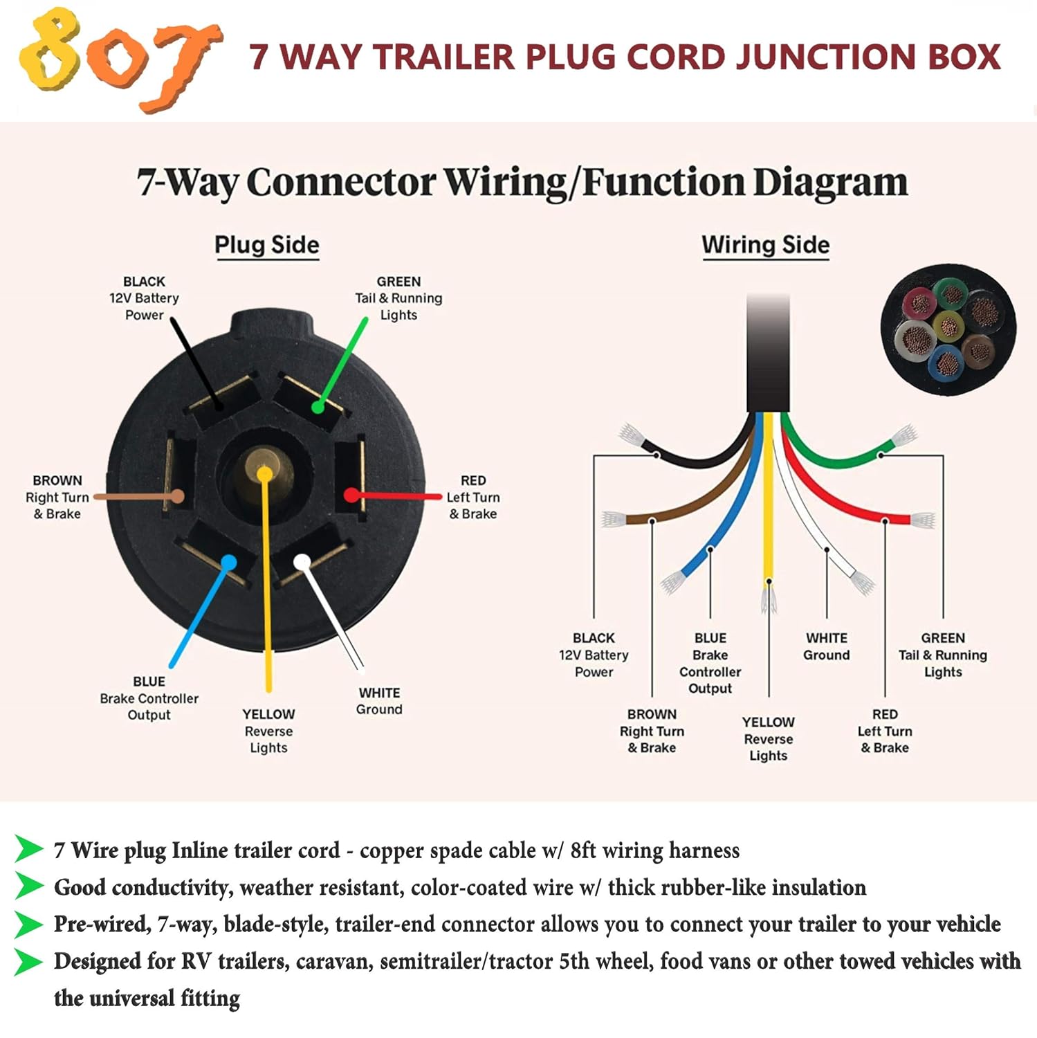
Each component ought to be set and connected with different parts in particular manner. 7 way plug wiring diagram standard wiring post purpose wire color tm park light green battery feed black rt right turn brake light brown lt left turn brake light red s trailer electric brakes blue gd ground white a accessory yellow this is the most common standard wiring scheme for rv plugs and the one used by major auto manufacturers today.
4 Axle Boatmate Trailer Planetnautique Forums

Trailer Wiring Diagrams Etrailer Com Trailer Light Wiring Trailer Wiring Diagram 5th Wheel Trailers

D Step Boat Trailer Steps Boat Accessories Boat Trailer Fishing Boat Accessories
2005 Boatmate Trailer 1650 Planetnautique Forums
Qowz 8385 Wabash 7 Way Trailer Plug Wiring Diagrammercial Wiring Diagrammercial Benjaman Home Shiseido Es

Best Boatmate Trailers For Sale Fishing Boat Accessories Boat Trailer Boat Accessories

Boatmate Trailer Parts Boat Mate Trailer Wheel Bearings Johnson Trailer Trailer Axles Trailer Plans

Trailer Breakaway Kit In 2020 Boat Trailer Parts Boat Trailer Lights Cheap Boats

Brake Rite Electric Hydraulic Actuator Complete Unit Towing Vehicle Complete Unit Hydraulic

Car Trailer Plans Professionally Designed All Parts Trailer Plans Car Trailer Car Hauler Trailer

Pin By Magnum Trailers On Magnum Custom Trailer Mfg Co Inc Boat Trailers Boat Trailer Boat Stuff

Are You Looking To Buy Trailer Wheels For Your Boat Boatmate Trailers Parts Section Is Stocked With Parts For All Tr Custom Trailers Buy Trailer Trailer Tires

Trailer Tail Lights Boatmate Trailer Company Boatmate Trailer

