Dot Trailer Wiring Diagram

Wiring Diagram For Semi Plug Google Search Trailer Light Wiring Trailer Wiring Diagram 5th Wheel Trailers

Wiring Diagram For Trailer Light 7 Pin Http Bookingritzcarlton Info Wiring Diagram For Trailer Light Trailer Light Wiring Trailer Wiring Diagram Car Trailer
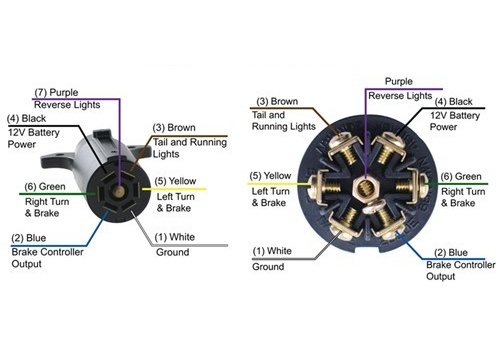
Diagram Dot Diagram 7 Wire Trailer Plug Full Version Hd Quality Trailer Plug Absolutewiring Fabricelefevreinstitut Fr

7 Blade Wiring Diagram Trailer Wiring Diagram Trailer Light Wiring Flatbed Trailer

7 Pin Trailer Plug Light Wiring Diagram Color Code Trailer Wiring Diagram Trailer Light Wiring Boat Trailer Lights

Trailer Wiring Diagrams For Single Axle Trailers And Tandem Axle Trailers Trailer Wiring Diagram Trailer Light Wiring Utility Trailer

Trailer wiring diagrams trailer wiring connectors various connectors are available from four to seven pins that allow for the transfer of power for the lighting as well as auxiliary functions such as an electric trailer brake controller backup lights or a 12v power supply for a winch or interior.
Dot trailer wiring diagram. When shopping for trailer connectors remember that the male end is mounted on the vehicle side and the female on the trailer side. 4 pin trailer wiring diagram. Below is the generic schematic of how the wiring goes. Click here to shop for trailer lights and wiring products.
In this section you will find information on legal requirements for trailer lighting wiring diagrams for 4 6 7 pole systems as well as some lighting terminology. The trailer wiring diagrams listed below should help identify any wiring issues you may have with your trailer. Only the blue brake and white ground wires are different. Trailer wiring diagrams trailer wiring connectors.
I have included a link to it. I do have a handy trailer wiring faq article that would be perfect for you. I have also included a picture that shows the typical wiring diagram of a 7 way round pin trailer side connector. Various connectors are available from four to seven pins that allow for the transfer of power for the lighting as well as auxiliary functions such as an electric trailer brake controller backup lights or a 12v power supply for a winch or interior trailer lights.
The image above shows a single axle trailer and the next image shows wiring for tandem axles. Some of the most basic maintenance practices can add years of service to your trailer lighting system. These 2 wire diagrams fit the needs of most trailers. Above we have describes the main types of trailer wiring diagrams.
Typical trailer wiring diagram and schematic. As you can see the 7 way round pin trailer connectors do not use the typical pin functions.

Trailer Wiring Diagrams For Single Axle Trailers And Tandem Axle Trailers Trailer Wiring Diagram Trailer Light Wiring Utility Trailer

Trailer Wiring Diagrams For Single Axle Trailers And Tandem Axle Trailers Trailer Wiring Diagram Trailer Light Wiring Utility Trailer

Wiring Diagram For Trailer Light 6 Way Http Bookingritzcarlton Info Wiring Diagram For Trailer L Trailer Light Wiring Utility Trailer Trailer Wiring Diagram

220v Single Phase Wiring Diagram 32 Wiring Diagram Wire Diagram Single

Wiring Diagram For Trailer Hookup Http Bookingritzcarlton Info Wiring Diagram For Trailer Hookup Trailer Light Wiring Trailer Wiring Diagram Car Trailer
Cdi Wiring Diagram Kill Switch Electrical Wiring Diagram Wire

Trailer Wiring Diagrams Trailer Wiring Diagram Enclosed Trailer Camper Enclosed Trailers

Unique Ac Wiring Color Diagram Wiringdiagram Diagramming Diagramm Visuals Visualisation Graphical Color Coding Diagram Coding

Car Trailer Wire Diagram Trailer Light Wiring Trailer Wiring Diagram Trailer

Trailer Wiring Diagrams Reboques Carretinha Carros

7 6 4 Way Wiring Diagrams Heavy Haulers Rv Resource Guide Trailer Wiring Diagram Rv Trailers Trailer Light Wiring

Rv Circuit Breaker Diagram Saferbrowser Yahoo Image Search Results Enclosed Trailers Trailer Light Wiring Trailer Wiring Diagram

Build Your Own Dump Trailer Dump Trailers Trailer Plans Homemade Trailer

